Saturday, March 22, 2008

Final Assembly


I hope you found the information in this blog useful. I will be starting another '48 that Will include the installation of all locks handles, glass. A complete concourse restoration. I have completed full size measured templates for most of the parts of this car and will make them available soon.
If you have any further questions please feel free to contact me through my website.There is a link on the front page of this blog.

I also want to thank Greg for all his help with this project.


Lift Gate / Tail Gate Assembly

The tail gate and lift gate are pretty basic in their construction. The upper and lower rail of the tailgate are set into the pillars on either side with through tenons. The middle stile is set into the upper and lower rail with tenons set approximately 3/4" deep. The quarter inch mahogany panels are fastened around their perimeter every 6 inches or so to the ash framework of the tail gate to keep everything stiff and square.
The lift gate was a bit more difficult because I didn't have either of the side pillars. The joinery is essentially the same as the tailgate, so using the curved back side of the rear quarter panel pillars, I was able to transfer the profile to the side pillars of the lift gate. The only other important aspect to figure out is the size of the rebate for the glass and that could be taken from the upper and lower rail as it is the same. While it is a basic type of joinery, care must be taken to avoid making mistakes. The cheeks of the tenons on the front and back side are off set to account for the rebates on the back side .
The only other reccomendation I might have would be to leave alittle material on the side pillars so they can be sanded down after being installed, to match the profile of the rear pillars.

Wednesday, March 12, 2008

Assembly Part II


I didn't have any good templates for the roof rails that run the length of the roof, and support the bows. I used a spacer block that would ride along the top rail of the rear quarter panel to make this section of the roof rails. I made four rails for each side, cutting the top and bottom with a bevel to match the originals. They then are fastened together from the inside with wood screws to complete the assembly. I continued working my way towards the front of the car in this manner.
There are two areas along the roof rails where they are finger jointed together. At each joint the roof rails angle in towards the middle of the car. At the front of the cab the rails enter the metal pillars on each side of the windsheild, and attach to the header where the roof and the front cowl meet.
Once I finished the assembly of the rails I attached the front header the the cowl and roof assembly, fitted the tenon at the top of the center door pillar . I then attached the roof rails to the upper rail of the rear quarter panel using screws through the window grooves, through the roof rails, and into t-nuts. Finally I fastened the T shaped bracts that hold the lift gate header, rear pillars and the roof rails together.
I had the piece of sheet metal for the front of the roof, so I used it to locate the forward most bow. Taking measurements from the original, I fastened the rest of the bows to the roof rails.
I started in the center with the roof slats, attaching them to the bows with #8 x .75" brass wood screws instead of the nails used originally. It helps to lay out the strips first, without fastening themsince they will be spaced apart slightly at the back and touching at the front

Monday, February 25, 2008

Begining Assembly

I started the assembly on the body by building the middle and rear supports for the rear deck. I then built the front support ( the one with the doors for accessing the bolts to the fender rails). I attached the large metal bracket at the rear that holds the rear main posts. I braced the rear posts in the proper position from front to back by bracing from the post to the fender rail (as seen in the picture. In order to hold the posts at their correct angle ( about 85 degrees from horizontal), I attached the lift gate header in position, then adjusted the posts from side to side until the angles taken from both sides, with a large bevel gauge, matched exactly. I made the cross brace from 1/4" plywood that was bolted through the center and screwed to both posts and the back cross support for the rear deck. This arrangement held everything real well while I built the rest of the rear quarter panels
I positioned the rear door latching post(the post that the door latches on as opposed to the hinge post) based on a number of points transferred from the original parts . I used the rear doors I had built along with the top rail of the rear quarter panel to accurately position the latching post. It is a good idea not to permanently fix anything until you are sure it is in the correct location. I had 95% of the car assembled before I drilled any of the through bolts that fasten the main joints together.
The structure of these cars is designed in such a way that the overall frame is joined with typical mortise and tenon type joinery that is held together with 1/4" or 5/16" bolts and blind nuts. This framework is then made rigid with the mahogany panels screwed around the perimeter at 2 1/2" to 4"on center to the frame.

Tuesday, January 15, 2008

Fender Rails


The partial fender behind the front fender, and the rear fender are mounted to fender rails that are both constructed in a similar way. They both are designed to follow the curve of the fender, which would be difficult to achieve using a single piece of wood. Joining wood end to end this way is normally going to be a relatively weak joint. The only effective surfaces to glue are the face grain, as opposed to end grain, which is pretty much useless to glue. A finger joint like the ones found on these parts is quite strong. To give you a better idea you can look at the fact that you have about 10 sq. inches of face grain glued for every 1 1/2" of thickness.
I made what I felt was an improvement over the original design on the rear fender rails.They are made up of two rails laminated together for an overall thickness of 3".The original rails had the finger joints aligned across the two sections. I think this was probably due more to the necessity of efficiency in production. I kept the joints in the same location on the outside sections of the rails to maintain the look of the original. On the inside sections of the rails I staggered the joints so the finger joints on one section would be supported by solid wood next to it.
Both of these pieces were very deteriorated, so I started by making full size templates from 1/4" plywood. I then marked out where the joints were located on each piece. I set up the finger joint cutter so that when the fingers were cut on one piece the mating piece was cut by flipping it upside down to minimize the number of set ups and adjustments that neede to be made. Once I got the sections joind together, I passed them through the surface planer taking light cuts just until the joints were perfectly level. This would ensure the glue joints between the two pieces would be as seemless as possible.
The partial fender rails on the front doors are made the same way, except they are not laminated like the rear fender rails. Although they are thicker at about 2" for about 13 sq. inches of glued joint surface.
At this point I trace the templates I made onto the glued up sections ,and cut them out on the bandsaw, leaving a little material outside the line to remove with the belt sander , and hand planer. Once this was done I transferred the thicknesses from the original to the new stock , again cutting out on the bandsaw and finishing with the belt sander.

Monday, January 14, 2008

Routing With A Template


Each of the doors has a curved groove that accepts the outside panel . It would be impossible to route this dado accurately by hand, so you will need to make a template that will guide the router's cutting bit along this line. These grooves are 3/8" wide, and approximately 1/2" deep .
There are two ways of using a template to cut an irregular dado like this. One way is to use a bearing guided bit like the ones shown earlier in this blog, except the bearing would be above the bit as opposed to below it. But a better way for this application would be to use a guide bushing that will allow your cutter to fit through it. As the guide bushing rides along the template the cutter makes a groove just off set from the template. To determine the amount of off set, you take the size of the bushing's outside diameter (5/8"), and subtract the dia. of the cutter (3/8"). Now you have determined the bushing is 1/4" larger than the cutter, you divide this in half . This will give you the off set of one side (1/8"). Knowing this, you will need to make the template Off set from the groove you want to make by 1/8".
Given the depth of the dado you are making, it will take a few passes to reach the full depth of 1/2". Guide bushing sets are available with about six or seven different size bushings to accomidate a variety of cutter sizes.
Most bushings will require your template to be at least 1/2" thick. Also another good way to determine the off set of your template is simply to set up the cutter in a bushing that fits closely but does not touch, attach a fence to a sacrificial piece of wood, make a shallow pass. Ensuring the bushing is staying in contact with the fence, as it will sometimes want to wander depending on the direction of your cut, measure the distance from the edge of the fence to the edge of the dado. This is your off set.
This technique is useful whenever you must route a dado that does not run parallel to any side of the piece being worked.

Replicating Complex Profiles


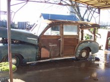
For the rail that runs the length of the car just below the windows, it was necessary to start by recreating the profile without the use of a shaper knife specially cut for this shape.
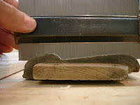
Begin by using a profile guide like the one shown here to copy the shape from a good cross section of the original stock. You can also trace the profile onto a piece of thick card stock.
Once you have the profile, dimension the stock for the left and right sides. Use the profile gauge to copy an outline onto the new stock. Take into account the shape you copy onto the new stock will be slightly smaller than the actual shape , so be sure not to remove the line, but work right up to the line.
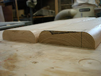
At this point using router bits and the table saw, work your way up to the line. Try to keep in mind what cuts will need to be made and do not cut away some part of the profile you will need to register against the fence for a later cut. Try to think a few steps ahead.
It is not important to follow the profile exactly, but each cut should touch the line you have drawn at some point.
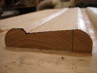
Once you have the shape roughed out, using a block plane, take off the remaining peaks, working your way down to the profile line. Try to make long, even passes down the length of the piece to ensure a consistent shape.Finally a few cabinet scrapers and some sanding should yield pretty good results.